| |
|
||||||
|
|
|||||||
|
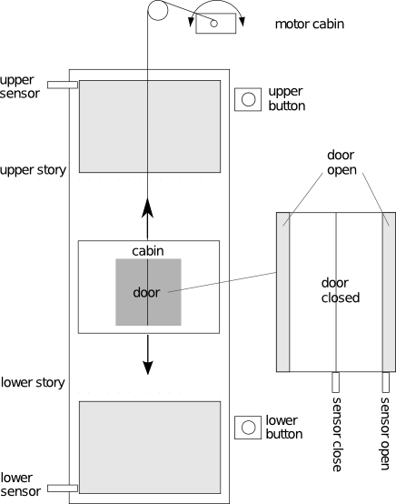
IODevice PlugInThe iodevice plug-in provides access to hardware components to the libFAUDES simulator such that the latter can synchronise with physical events and physical time. This section gives an introduction by means of a laboratory case study, designed by Thomas Wittmann as part of his student project, including the hardware realisation of a plant (simulation by analog circuits) and a supervisor (running simfaudes on an IPC). General documentation on the iodevice PlugIn is given at device types and through the more technical IODevice C++ API referencedocumentation. Physical PlantOur example addresses a simple goods lift that shuttles between two levels. The below figure on the left shows the basic configuration, consisting of the cabin, the cabin door and two push buttons, one on each level.
The physical plant interface consists of input- and output signals, listed in the above tables, where the terminology is used from the controller persepctive. Each signal can be active or passive, i.e. exhibits a boolean range. The bit address given in the last column refers to the LRT laboratory setup and specifies how the respective signal is accessed from the connected controller device. Example, controller output. The cabin motor is controlled by two signals Y_CM_UP and Y_CM_DN, where the active level correspond to upwards and downwards motion of the cabin, respectively. Example, controller input. The upper operator push button corresponds to the signal U_OP_UP, which is active while the button is pressed. For the purpose of supervisory controller design, the continuous dynamics of the cabin and the door are regarded irrelevant. For the LRT lab experiment, the mechanical setup is replaced by an analog circuit connected to the controller device. Plant ModelIn order to model the physical plant as a discrete event system, we need to define relevant events. Here, we assume the continuous signal to be piece-wise constant and associate events with edges of specific signals. An input event is triggered by the plant when the associated output signal changes its value (positive or negative edge). In contrast, an output event is triggered by the controller and sets (or clears) the value of associated plant-input signals to active (or, respectively, passive). See SignalDevice for details. The below table defines events related to the cabin and the operator push-buttons, a complete list can be found on the further-details-page.
In order to formally introduce the above events and their semantics to libFAUDES, a device configuration file has to be provided. In addition to the above definitions, the configuration file is used to specify a sampling period for edge detection and further device specific details. A device configuration file for the elevator example is given on the further-details-page. The discrete behaviour of the physical plant is modelled by three independent Generators for the components cabin, door and operator. The cabin component G_cabin is given below, the remaining components are gathered on the further-details-page.
Controller SynthesisThe plant model exhibits any possible behaviour of the elevator scenario, including unacceptable behaviour, e.g. not turning of the cabin motor when arriving an the upper position. We give verbal conditions for acceptable event sequences regarding the cabin and the operator buttons.
The above conditions 1 and 2 amount to the formal specification E_cabmot, whereas condition 3 is represented as E_opcmd:
A supervisor can be synthesised by calling the function SupCon, where the plant and the specification are given as arguments. For the cabin and the above basic shuttle behaviour, the result is shown below. A luafaudes script for the entire elevator scenario including the door is given on the further-details-page.
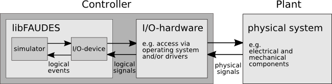
Hardware-In-The-Loop SimulationThe libFAUDES simulator can utilise the iodevice plug-in to simulate the supervisor and to synchronise events with the physical plant. This setting, is referred to as hardware-in-the-loop simulation, and the computer (e.g. PC) that executes the simulator plays the role of the controller.
The command-line tool iomonitor is used to inspect the hardware configuration, i.e. to test whether logical events are mapped to physical events as intended. After reading the device configuration file, iomonitor provides a text based user interface to get and set signal levels, to detect input events and to execute output events. Example: $ cd ./libfaudes/plugins/iodevice/tutorial $ iomonitor data/elevator_pio.dev # available commands are: # read faudes events (er) # read signal value by bitaddress (sr) # write faudes events (ew) # write signal value by bitaddress (sw) # device time (time) # reset device (reset) # list all device events (list) # exit (exit) > Note: the signal based interface (sr) and (sw) is only available for devices derived from the SignalDevice base class. In particular, this excludes container devices. The latter are more conveniently tested per individual device. After validating the configuration, a hardware-in-the-loop simulation can be performed with the simfaudes tool. In addition to the configuration options and simulation semantics discussed in simulator plug-in, the simulator accepts a device configuration file specified by the command-line option -d. To start the simulation, enter $ cd ./libfaudes/plugins/iodevice/tutorial $ simfaudes -d data/elevator_pio.dev data/elevator_super_core % simfaudes: ========================================= sync with "LrtElevatorIO" % simfaudes: ========================================= device "LrtElevatorIO" is up % simfaudes: ========================================= current state: <DiscreteState> 1 </DiscreteState> % simfaudes: ========================================= current time: <Time> 0 </Time> % simfaudes: ========================================= proposed action: <ProposedTime> inf </ProposedTime> % simfaudes: ========================================= sync wait In the initial state, the simulator cannot execute any output event, hence it waits for an input event, e.g. o_upb. The synchronisation procedure is summarised in DeviceExecutor. Further Documentation of the Elevator ExampleA full version of the required input data is provided on the further-details-page. Thomas Wittmann's final report is also available from the libFAUDES archive. libFAUDES 2.33h --- 2025.09.16 --- with "synthesis-omegaaut-observer-diagnosis-iosystem-hiosys-multitasking-coordinationcontrol-timed-iodevice-priorities-simulator-luabindings" |