| |
|
|||||||
|
|
||||||||
|
DevicesThe iodevice plug-in provides data-types that access hardware components to enable hardware-in-the-loop simulation, i.e., to run a supervisor on a physical plant. The devices implemented in this version of libFAUDES are motivated by LRT laboratory equipment, adaption to other hardware components should be straight forward. Each device is configured by a libFAUDES token stream to map physical events (external events) to logic events (libFAUDES events). The prototypical example for a device is the SignalDevice, which interprets edges of electrical signals connected via a digital IO board as physical events. In general, devices distinguish between events that are triggered externally and events that are to be triggered internally. For the SignalDevice this amounts to input events which indicate edges sensed on a digital input signal and output events that impose edges on a digital output signal. Devices also provide a clock referring to physical time. A simulator application may use this feature to synchronise the internal clocks of a timed automaton with physical time. The clock provided by a device refers to faudes time-units (ftu) since initialisation, where a scaling factor with unit ms/ftu is set at device configuration. To inspect a libFAUDES device independently from the simulator, the tool iomonitor provides a simple command line interface to report input events and to trigger output events. There is also the iobridge to associate the respective events of two devices, which in conjunction with the SimplenetDevice can be used to implement PC based operator interfaces and/or process visualisation. Technical Note: since hardware access typically depends on low-level libraries, individual devices must be explicitly enabled by compile-time switches in the Makefile libfaudes/plugins/iodevice/Makefile.plugin. SignalDeviceAbstract interface for signal based event detection and execution.
A SignalDevice maps libFAUDES events (logical events) to edges on digital signals (physical events). It is an abstract data-type in that it does not implement actual hardware access. This is left to derived types, which in the standard libFAUDES distribution amounts to the ComediDevice, the SpiDevice, and the ModbusDevice. SignalsEach individual signal is identified by an abstract bit-address which corresponds to a particular port/pin/connector of the underlying hardware. We assume all signals to exhibit a boolean range, i.e. at each instance on time the signal takes one of two values, referred to as high/low, active/passive or true/false. A signal may either be an input signal or an output signal depending on whether we can read or write its current value from the underlying hardware. Input signals and input eventsEach input signal is monitored periodically to detect edges. An input event is defined by its trigger sources given as a list of bit-addresses and edge polarities. Whenever a specified edge occurs, the simulator is notified about the occurrence of the respective event. The below fragment of a device configuration defines the logical event alpha to be triggered by either a positive edge (from low to high) on the signal with address 4 or a negative edge (from high to low) on signal 7. Note that, if both edges occur within one sampling period, only one event alpha will be issued. <Event name="alpha" iotype="input"> <Triggers> <PositiveEdge address="4"/> <NegativeEdge address="7"/> </Triggers> </Event> Technical Detail. Edge detection is implemented by a cyclic background thread that takes a sample of the input line-levels. At the end of every cycle, a timer is used to wait for the sampling interval to elapse. The sampling interval can be set by the configuration tag <SampleInterval value="xxx"/>, where xxx is the period in usecs. An error is reported, whenever the schedule cannot be met. Output signals and output eventsAn output event is defined by a list of actions that set, clear or invert the value of a particular output signal specified by its bit-address. Whenever the simulator executes the respective event, the affected signal values are set accordingly. The below configuration example configures the logical event beta to clear the signal with address 1 to low, to set signal 8 to high, and to invert the signal with address 9. Note that inverting a signal is only supported in conjunction with the synchronous write option (enabled by the <SynchronousWrite/> tag in the configuration file, see also below). <Event name="beta" iotype="output"> <Actions> <Clr address="1"/> <Set address="8"/> <Inv address="9"/> </Actions> </Event> Technical Detail. Output events and their effect on the respective line-levels can either be perfromed synchonously or buffered by a line-level buffer for subsequent application by the background thread. Buffered outputs are automatic for most derived classes or can be enforced explicitly by the <SynchronousWrite/> tag. With synchronous write, the overall line-level buffer for input- and output-lines represents the so called process image. Token IOConfiguration details depend on the supported hardware and are documented in the derived types, e.g. ComediDevice. ComediDeviceAccess digital IO hardware within the comedi framework.
A ComediDevice object is a SignalDevice that uses low-level drivers from the comedi-framework to access digital-I/O hardware. Available drivers include specialised PCI extension boards for automation as well as generic parallel I/O boards. Low-level configurationThe comedi-framework provides a command line tool to configure the actual hardware that henceforth can be accessed via the system files /dev/comedi0, /dev/comedi1, /dev/comedi2, etc. Detailed instructions on supported hardware and the installation procedure are given on the comedi site. As an example, we provide a configuration script for the LRT laboratory PC equipped with two Advantech digital IO PCI boards: #!/bin/sh # Configure the comedi kernel module to run the LRT lab experiment. echo 1. ========= load advantech module /sbin/modprobe adv_pci_dio echo 2. ========= setting up device comedi_config /dev/comedi0 -r comedi_config /dev/comedi1 -r comedi_config /dev/comedi0 pci1754 2,5 comedi_config /dev/comedi1 pci1752 2,9 echo 3. ========= running test comedi_test --device /dev/comedi0 comedi_test --device /dev/comedi1 echo 4 ========== report comedi_info -f /dev/comedi0 comedi_info -f /dev/comedi1 See also ./libfaudes/plugins/iodevice/tutoral/data for a version of this script that cares about Linux user privileges. Event-mapping configurationComediDevice objects inherit the event-mapping mechanism introduced by the SignalDevice. To configure the event-mapping you must supply the system device file, the sampling period for edge detection, and event definitions as described for the SignalDevice. The bit addresses 0 corresponds to the lsb of the first low-level data word and counts up to the number of available signals minus 1. An example configuration is given below. Token IOThe example configures a ComediDevice to access the digital input port of the LRT lab Advantech PCI1754 via /dev/comedi0 and sense edges on signal #4. <ComediDevice name="LrtInputDevice"> <!-- Time scale in ms/ftiu --> <TimeScale value="500"/> <!-- Sample interval for edge detection in usec --> <SampleInterval value="1000"/> <!-- Sytem device file --> <DeviceFile value="/dev/comedi0"/> <!-- Trigger based event definitition to follow --> <EventConfiguration> <!-- Event "alpha" to indicate a positive edge on signal #4--> <Event name="alpha" iotype="input"> <Triggers> <PositiveEdge address="4"/> </Triggers> </Event> <!-- Event "beta" to indicate a negative edge on signal #4--> <Event name="beta" iotype="input"> <Triggers> <NegativeEdge address="4"/> </Triggers> </Event> <EventConfiguration/> </ComediDevice> Note: this device must be explicitly enabled in the Makefile libfaudes/plugins/iodevice/Makefile.plugin WagoDeviceAccess digital IO hardware by Wago Kbus interface.
A WagoDevice object is a SignalDevice that accesses digital signals via the WAGO-kBus. The latter is used in WAGO IPCs to attatch IO modules. Signal values are read from and written to the so called process image, organized in two separate arrays of input bytes and output bytes. The bit layout depends on the IO modules present and their physical position on the kBus (so called slot). It can be inspected by running cat /proc/driver/kbus/pab , e.g. using a telnet connection to the IPC. Further details on the bit layout are provided by original documentation from WAGO. For the purpose of configuring a WagoDevice Object, each of the two byte arrays are interpreted as consecutive bits. Thus, the WagoDevice bit-address addr corresponds to bit number addr % 8 within the process image byte with offset addr / 8. The WagoDevice is used for the LRT elevator lab experiment, a corresponding configuration file is supplied in the tutorial section and controller synthesis is discussed in simulator user reference. The experiment was designed by Thomas Wittmann as part of his student project. Kind support by WAGO is greatefully acknowleged. 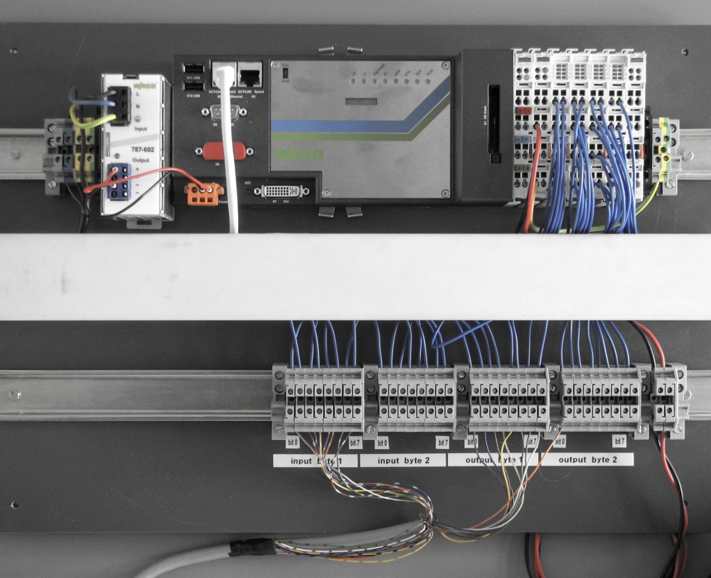
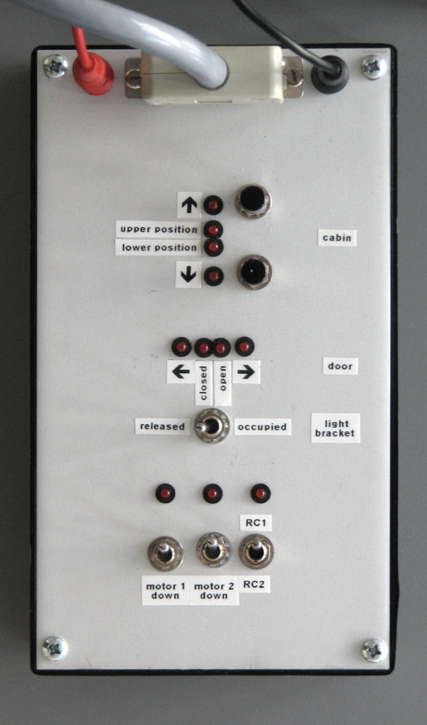
LRT laboratory setup: WAGO IPC as supervisor with harware plant simulator Note: this device must be explicitly enabled in the Makefile libfaudes/plugins/iodevice/Makefile.plugin and requires the separate installation of low-level kbus libraries. The latter can be obtained from WAGO. Note: The current implementation is restricted to one WagoDevice object per IPC. Thus, you may not run multiple applications that use the WagoDevice class to access the process image. SpiDeviceSynchronize process image via serial interface.
An SpiDevice object is a SignalDevice that emulates component interconnection to behave like parallel digital wiring, however, physically using the serial interface to synchronize the process image. The latter is a vector of boolean values that represents the line levels of the emulated digital wiring. The SpiDevice distinguishes between one master component and an arbitrary number of slave components. The master must be physically connected to each slave via a dedicated serial interface. At each sample period, the master passes the process image consecutively to each client, which in turn overwrites the respective ouput line levels and reports back the manipulated image. In particular, any bit in the process image should represent an output signal for exactly one component. 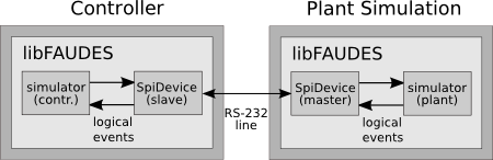
Closed loop configuration with simulated plant connected via SpiDevice The above figure illustrates the interconnection of a controller with a plant simulation, each on a seperate PC. As a variation, one may implement the plant simulation on a microcontroller for class-room experiments. Since there can be multiple slave compoments, the scenario is readily extended to decentralized control; see also Simulator Interconnection. To configure an spiDevice, you must
Technical Detail. In the current implementation, the process image has a fixed length of 64 bits and the serial line is configured to operate at 115200 bits per second. This suggests an overall time for serial transmission of about 1ms per slave. Consequently, the sampling time for a slave component should by set to 1ms. Due to a very naive mechanism used for the detection of blocks of consecutive data, the sampling time for the master should not be below 5ms per slave. Token IOThe example configures the SpiDevice for a plant simulation with master role. The process image is synchronized with two slaves connected via /dev/ttyS1 and /dev/ttyS2. At bit address 0, the process image controls an actuator, e.g., a motor to run a machine. At bit address 1, the process image indicates a sensor state, e.g., a switch that indicates completion of a positioning task. <SpiDevice name="Plant Simulation"> <!-- Time scale in ms/ftu --> <TimeScale value="1000"/> <!-- Sample interval for edge detection in us (10ms) --> <SampleInterval value="10000"/> <!-- Role: master --> <Role value="master"/> <!-- Sytem device files --> <DeviceFile value="/dev/ttyS1"/> <DeviceFile value="/dev/ttyS2"/> <!-- Trigger based event definitition --> <EventConfiguration> <!-- Actuator (plant input) --> <Event name="op_start" iotype="input"> <Triggers><PositiveEdge address="0"/></Triggers> </Event> <Event name="op_stop" iotype="input"> <Triggers><NegativeEdge address="0"/></Triggers> </Event> <!-- Sensor (plant output) --> <Event name="op_inprog" iotype="output"> <Actions><Set address="1"/></Actions> </Event> <Event name="op_complete" iotype="output"> <Actions><Clr address="1"/></Actions> </Event> </EventConfiguration> </SpiDevice> Note: this device must be explicitly enabled in the Makefile libfaudes/plugins/iodevice/Makefile.plugin ModbusDeviceSynchronize process image via Modbus/TCP protocol.
The ModbusDevice class is derived from the signal based SignalDevice to read and write line levels via ethernet using the Modbus/TCP protocol; see the Modbus Organization for techincal details. A ModbusDevice can be either configured as a slave or as a master. Typically, a PLC will be configured as master and initiate communications with I/O devices, which behave as slaves. Event semenatics are inherited from SignalDevice and refer to a local copy of the remote process image. The Modbus/TCP integration to libFAUDES was driven by the factory simulator FlexFact from the applications project and has been tested extensively in this particular context. If you experience problems in accessing other Modbus/TCP devices, please let us know, so we can improve our implementation. MasterWhen configured as master, the ModbusDevice initiates commucation with a specified list of slaves in order to retrieve input line levels and to set output line levels. The latter are locally buffered and propagated to the event-based interface inherited from SignalDevice. To configure a ModbusDevice as a master, use the role tag <Role value="master"/> and specify the remote slave address by <SlaveAddress value="hostname:port"/>. Here, hostname can be given as an IP address in dot-notation or as a alpha-numerical hostname for the operating system to resolve. By the Modbus specification, the port should be 502. However, this requires root privileges on some systems, and a common fallback is the unpriviledged port 1502. A ContainerDevice can be used to access multiple slaves by different IP addresses. Once per cycle of the SignalDevice background thread, the ModbusDevice will synchronize the local line-level buffer with the remote slave. The correspondence between remote bit addresses and the bit addresses used in the local buffer is defined by the <RemoteImage> element. You may specify ranges of <Inputs> or <Outputs> and use the following attributes to declare the address mapping:
The below example configures a master to access the simple machine plant from the decentralized control example. It expects the plant in slave role to provide a process image with remote address range from 0 to 3, where bit 0 and 2 are plant inputs and 1 and 2 are plant outputs. The remote image is mapped 1:1 to the internal line-level buffer. <ModbusDevice name="plant access"> <!-- SignalDevice configuration --> <TimeScale value="10"/> % 1000 msec per ftu <SampleInterval value="5000"/> % 5000 usec <!-- Modbus slave configuration --> <Role value="master"/> <SlaveAddress value="localhost:1502"/> % slave at localhost:1502 <!-- Modbus address mapping: map 1:1 --> <RemoteImage> <Inputs mbaddr="0" count="4" /> <Outputs mbaddr="0" count="4" /> </RemoteImage> <!-- SignalDecive events --> <EventConfiguration> <!-- Plant inputs on line 0 and 2 --> <Event name="p_start" iotype="output"> <Actions> <Set address="0"/> </Actions> </Event> <Event name="m_start" iotype="output"> <Actions> <Set address="2"/> </Actions> </Event> <!-- Plant outputs on line 1 and 3 --> <Event name="p_inprog" iotype="input"> <Triggers> <PositiveEdge address="1"/> </Triggers> </Event> <Event name="p_complete" iotype="input"> <Triggers> <NegativeEdge address="1"/> </Triggers> </Event> <Event name="m_request" iotype="input"> <Triggers> <PositiveEdge address="3"/> </Triggers> </Event> <Event name="m_complete" iotype="input"> <Triggers> <NegativeEdge address="3"/> </Triggers> </Event> </EventConfiguration> </ModbusDevice> Technical Detail. The ModbusDevice allows for a relaxed configuration style in that it never overwrites line levels that correspond to its output lines, i.e., when reading from the remote slave, values that correspont to local output lines will be silently ignored. As in the above example, one may map the entire process image to the internal buffer, regardless of the input/output role of individual lines. For obvious reasons, this relaxed configuration style can only be used when the respective slaves behave in the same manner. Technical Detail. Network I/O is implemented synchronous with the edge detection background thread of the SignalDevice. Thus, the minimum response delay for the master is its SamplingInterval. Consequently, the slave should sample at a reasonably lower rate as the master. Future implementations may seperate edge detection and Modbus communication to circumvent this issue. SlaveWhen configured as slave, the ModbusDevice accepts connections from any Modbus master, will response to their request and update the local line-level buffer accordingly. Possible applications include a line-level based interconnection of a PLC in Modbus master mode with an instance of simfaudes for plant simulation. To configure a ModbusDevice as a slave, use the role tag <Role value="slave"/>. The port, on which the ModbusDevice listens for connections defaults to 502 and can be explicitly set by <SlaveAddress value="localhost:port"/>. In the current implementation, the slave ignores the Modbus-id and maps the internal buffer 1:1 to Modbus bit addresses. At the time of writing, slave mode has only be tested by monitoring the decentralized control example and may not be functional in other scenarios. The below example configures a slave to provide line-levels of the simple machine plant from the decentralized control example. It expects the supervisor (or iomonitor) to connect in master mode and to retrieve plant outputs at address bit 1 and 3 and to set plant onput bits at address 1 and 2. <ModbusDevice name="plant simulator"> <!-- SignalDevice configuration --> <TimeScale value="1000"/> % 1000 msec per ftu <SampleInterval value="1000"/> % 1000 usec <!-- Modbus slave configuration --> <Role value="slave"/> <SlaveAddress value="localhost:1502"/> % listen on port 1502 <!-- SignalDecive events --> <EventConfiguration> <!-- Plant inputs on line 0 and 2 --> <Event name="p_start" iotype="input"> <Triggers> <PositiveEdge address="0"/> </Triggers> </Event> <Event name="m_start" iotype="input"> <Triggers> <PositiveEdge address="2"/> </Triggers> </Event> <!-- Plant ioutputs on line 1 and 3 --> <Event name="p_inprog" iotype="output"> <Actions> <Set address="1"/> </Actions> </Event> <Event name="p_complete" iotype="output"> <Actions> <Clr address="1"/> </Actions> </Event> <Event name="m_request" iotype="output"> <Actions> <Set address="3"/> </Actions> </Event> <Event name="m_complete" iotype="output"> <Actions> <Clr address="3"/> </Actions> </Event> </EventConfiguration> </ModbusDevice> To test the ModbusDevice, you may open two console windows to run > simfaudes -d data/decdemo_plant_modbus.dev data/decdemo_plant.sim > iomonitor data/decdemo_test_modbus.dev This will simulate the plant from the decentralized control example and access its process image by the iomonitor. Note: this device must be explicitly enabled in the Makefile libfaudes/plugins/iodevice/Makefile.plugin SimplenetDeviceNetwork based communication of events.
The SimplenetDevice sends and receives events in form of messages over a digital communication network. Together with the simulator plug-in, in can be used to implement decentralized supervision of discrete event systems. However, a very pragmatic approach is taken and the SimplenetDevice must not be confused with ongoing research that addresses synchronisation, real time behaviour, re-configuration, etc. Network, Client, Server and Protocol
Network:
A network is identified by its network name.
A network consists of a number of nodes, each identified by its node name.
Each node is aware of the entire network, i.e. the node names of all participating
nodes.
Each node implements both
Server: In its server role, the node sends event notifications whenever an output event is executed. The node is configured to listen on its server port for incoming network connections. It replies to a simple set of commands to allow a connecting client to subscribe to the nodes output events. Client: In its client role, the node receives event notifications for its input events. For each input event, there must exist some node, where the respective event is an output event. The client connects to all other nodes and subscribes to their output events. When it receives an event notification, this is interpreted as an input event. Protocol: The message protocol used for commands and notification is faudes-token based and uses the carriage-return ASCII code 0x0d to separate messages. Messages are sent and received over TCP connections, and can be inspected/generated with standard network tools like nc or telnet; see also the tutorial shell scripts. For each node, the server port must be set by the configuration tag <ServerAddress value="localhost:port"/>, where port is the number of the TCP port to listen on, i.e., the port to which clients may connect to subscribe events. If more than one node is meant to run on the same host, each must be configured to listen to a different port. Further details regarding the protocol are given in the IODevice C++ API documentation. Technical Detail: Server addresses are distributed to all nodes via UDP broadcasts. This mechanism requires all hosts to reside in the same subnet. If for some reason address resolution fails, each node must be explicitly configured to be aware of each other server address. This is achieved by supplying appropriate address attributes for each node in each configuration file; e.g. <Node> name="SimpleSupervisor" address="192.168.2.1:40000"</Node>. Token IOFor token IO, the SimplenetDevice reads and writes a section with label "SimplenetDevice". There are no relevant attributes yet. Simple machine example: <SimplenetDevice name="SimpleMachine"> <!-- Time scale in ms/ftiu --> <TimeScale value="1000"/> <!-- IP address of this node, incl. server TCP port --> <ServerAddress value="localhost:40000"/> <!-- Broadcaset address for address resolution (optional) <BroadcastAddress value="255.255.255.255:40000"/> <!-- Network topology --> <Network name="SimpleLoop"> <Node name="SimpleMachine"/> <Node name="SimpleSupervisor"/> </Network> <!-- Event configuration --> <EventConfiguration> <Event name="alpha" iotype="input"/> <Event name="beta" iotype="output"/> <Event name="mue" iotype="output"/> <Event name="lambda" iotype="input"/> </EventConfiguration> </SimplenetDevice> Note: this device must be explicitly enabled in the Makefile libfaudes/plugins/iodevice/Makefile.plugin D3RipUrtDeviceSynchronize events via D3RIP protocols.
The D3RIP protocol family has been developped by Klaus Schmidt and Ece Schmidt to address communication requirements from decentralized industrial automation, including dynamic bandwidth allocation for hard real-time guarantees. A software implementation using low-cost Ethernet hardware is available from the developers. For further information, please contact Ece Schmidt. The D3RipUrtDevice class provides a libFAUDES interface to the D3RIP URT protocol, to be used e.g. for the synchronization of events among multiple instances of simfaudes for the decentralized supervision of discrete event systems; see also Simulator Interconnection. The libFAUDES interface has been implemented by Ulas Turan in course of his Msc Thesis project. Token IOD3RipUrtDevice objects identify input-events and output-events by a unique id, which must be configured accordingly. In addition, output-events must be assigned with protocol specific parameters; see D3RIP for further details. Example configuration of a controller node: <D3RipUrtDevice name="ControllerB_Net"> <TimeScale value="1000"/> <EventConfiguration> <Event name="?lambda" iotype="output"> <EventId value="1"/> <ChannelToTransmit value="1"/> <ParameterRecord name="11"> <DestinationNode value="1"/> <DestinationChannel value="1"/> <EligibilityTime value="2" /> <DeadlineTime value="5"/> </ParameterRecord> </Event> <Event name="!lambda" iotype="input"> <EventId value="2"/> </Event> <Event name="lambda" iotype="output"> <EventId value="3"/> <ChannelToTransmit value="1"/> <ParameterRecord name="11"> <DestinationNode value="2"/> <DestinationChannel value="1"/> <EligibilityTime value="2" /> <DeadlineTime value="5"/> </ParameterRecord> </Event> </EventConfiguration> </D3RipUrtDevice> Note: This device must be explicitly enabled in the Makefile libfaudes/plugins/iodevice/Makefile.plugin. It imposes a number of requirements on your software infrastructure. You will need (1) a D3RIP implementation; (2) an IEEE 1588 synchronization deamon; and (3) a real-time patched Linux kernel. DeviceContainerMerge individual IO devices.
The DeviceContainer merges individual devices to behave like a single device. Input readings are combined in a union fashion over all participating devices, output writings are dispatched to the respective device. Typical applications are distributed control systems where controller components that interact with the physical plant via a SignalDevice also need to synchronize with other controllers via a SimplenetDevice. The DeviceContainer may also be used to access multiple independant signal devices. Token IOFor token IO, the DeviceContainer consists of a list of individual device configurations. The example uses two ComediDevices to access two PCI parallel IO boards. <DeviceContainer name="LrtLabSignalIO"> <!-- Common time scale in ms/ftiu --> <TimeScale value="10"/> <!-- List of devices --> <Devices> <!-- Device for Input signals resp. events --> <ComediDevice name="LrtLabInputDevice"> <SampleInterval value="100"/> <DeviceFile value="/dev/comedi0"/> <EventConfiguration> <Event name="SensorA+" iotype="input"> <Triggers> <PositiveEdge address="26"/> </Triggers> </Event> <Event name="SensorA-" iotype="input"> <Triggers> <NegativeEdge address="26"/> </Triggers> </Event> </EventConfiguration> </ComediDevice> <!-- Device for Output signals resp. events --> <ComediDevice name="LrtLabOuputDevice"> <SampleInterval value="100"/> <DeviceFile value="/dev/comedi1"/> <EventConfiguration> <Event name="MotorA+x" iotype="output"> <Actions> <Clr address="28"/> <Set address="26"/> </Actions> </Event> <Event name="MotorA-x" iotype="output"> <Actions> <Clr address="26"/> <Set address="28"/> </Actions> </Event> <Event name="MotorAstp" iotype="output"> <Actions> <Clr address="26"/> <Clr address="28"/> </Actions> </Event> </EventConfiguration> </ComediDevice> </Devices> </DeviceContainer> libFAUDES 2.34g --- 2026.04.28 --- with "omegaaut-synthesis-observer-observability-diagnosis-hiosys-iosystem-multitasking-coordinationcontrol-timed-simulator-iodevice-priorities-luabindings-hybrid-example-pybindings" |